Report on Aircraft Propulsion System
Number of words: 2693
This report provides an analysis of different types of gas turbine engines and the environmental impact of the gas turbine engine. In addition, other literature and data have been studied to understand different types and modules in gas turbine engines. The environmental impact of the gas turbine engine has been presented in three categories: in-flight operations, airport operations, and manufacturing and disposal. In addition, the report illustrates new technologies that have been implemented to reduce environmental impact and increase sustainability. The scope of propulsion technology in aviation is vast; however, the data produced in the report is brief due to the limits of the report.
Introduction
Flying has been a fascination for humankind for ages, from the myth of wax glued feather wings of Icarus to the flying machine of Da Vinci. This fascination led to the invention of air balloons in mid-220 AD, and the first manned flight in the air balloon was in 1783 (Crouch, 2009). In the perspective of aviation, the propulsion power to sustain human flight was provided by a compact petrol engine in the early 20th century. The capacity of the engine was 80 kg, and it supplied 9 kW to the twin-propeller. The father of aerodynamics, Sir George Cayley, laid the foundation of forces required for flying in 1799, the fixed-wing flying machine, a separate mechanism for lift, an engine for propulsion, and the controls (Hunsaker and Pritchard, 1963). Unlike land vehicles, surface vessels, and spacecraft, an aerodynamic flight requires permanent propulsion. The modern propulsion system for an aircraft is achieved by the jet engines that compress air in the first stage and expand it through its turbine blade to provide higher speed. The integral part of the jet engine is a gas turbine. This report aims to study different types of gas turbine engines and new sustainable technologies to reduce environmental impact. This report illustrates four main types of gas turbine engines followed by a brief description of two essential modules, i.e., compressor and turbine. The report also discusses the environmental impact of the gas turbine engine, followed by new technologies that helped reduce the environmental impact.
Types of the gas turbine engine
The gas turbine engine is used widely in the aviation industry for propulsion. There is various type of gas turbine engines available in the market. However, they are classified into four different types based on the flow in the compressor, air path in the engine, and production of power. Thus, four types of gas turbine engines powers aircraft: turbojet, turboprop, turbofan, and turboshaft (Farokhi, 2014).
Turbojet engine
Germany and England developed a turbojet engine before world war II. The turbojet engine is straightforward as compared to other jet engines. Figures 1 and 2 show the section and schematic layout of the turbojet engine, respectively. The turbojet engine has four stages: air intake, compression, combustion, and exhaust (Farokhi, 2014).
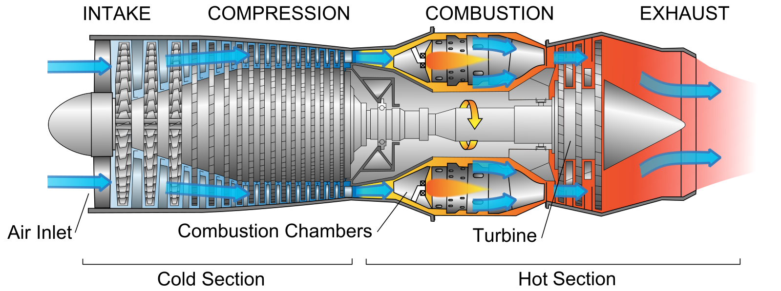
Figure 1: Section in turbojet engine (Cutler, 2017)
The air intake is accomplished through a series of tubes that directs air to the compressor blades. The compression is accomplished by the compressor, which is driven by the turbine; the compressor has different stages (Lowe pressure to high pressure) that compresses air to the maximum air pressure before it enters into the combustion chamber. The compressed air is mixed with the fuel that ignites the mixture and moves towards turbine blades. The fuel mixed with compressed air is very lean, approximately in the ratio of 50 to 1. The turbine then expands the gases by converting the heat energy of the ignited mixture to high-speed rotation, as gases are passed over the turbine blades. Turbine blades are mounted over the shaft, and this shaft is connected to the compressor. The temperature air-fuel mixture exhaust from the nozzle to produce thrust, and according to Newton’s third law, it pushes the aircraft in the opposite direction. The advantages of these engines are that they are simple in their design, occupy little space, and produce high speed. However, they have high fuel consumption, are very loud, and at low speed, they have poor performance. Also, the compressor speed is comparatively slow, has limited range as well as endurance. Therefore their application is restricted to the military application (Farokhi, 2014).
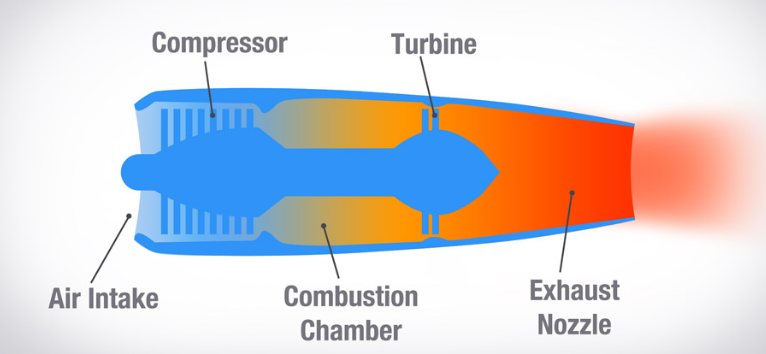
Figure 2: Schematic diagram of the turbojet engine (Cutler, 2017)
Turboprop engine
The first turboprop engine was designed by Hungarian designer Gyorgy Jendrassik between 1939 and 1942. Unfortunately, the turboprop design was not implemented until 1945 when Rolls Royce developed Derwint II into RB50 Trent. The turboprop is a combination of the propeller, gas turbine engine, and a reduction gearbox. Figure 3 shows the schematic arrangement in the turboprop engine. The working principle of the turboprop engine is the same as the jet engine with the addition of the propellers and reduction gearbox. In addition, there is one extra stage incorporated to drive the propeller. The turbine transmits the power to the propeller through a reduction gearbox. The reduction gearbox is necessary as the propeller performs better at a lower speed than engine rpm. The turboprop engine can be broken into four assemblies, the power section that contains the compressor, combustion chamber, turbine, and exhaust; Reduction gearbox; torque meter that provides torque from the jet engine to the reduction gearbox; and the accessories drive housing that houses all the gear trains and air inlet (Farokhi, 2014).
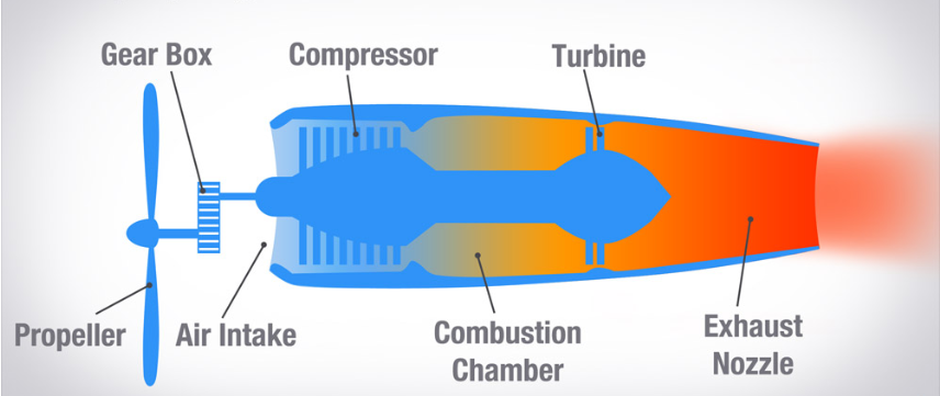
Figure 3: Schematic diagram of the turboprop engine (Cutler, 2017)
Figure 4 shows the king air aircraft equipped with a turboprop engine. The jet engine produces power, and the power is provided to the propeller through a reduction gearbox. The gearbox reduces the rpm, which is coupled with the propellers. The propellers then turn to produce the thrust (Cutler, 2017).
A turboprop engine is very fuel-efficient, especially at the mid-range speed of 250-400 knots and mid-range altitude of 18000 to 30000 feet. The only limitation is the limited forward airspeed and the possibility of the gear system breakdown.

Figure 4: Aircraft propulsion with turboprop engine (Cutler, 2017)
Turbofan engine
The turbofan engine combines the turboprop and turbojet engine, and the schematic layout is shown in figure 5 below. The design of the turbofan engine diverts the secondary airflow around the combustion chamber creates the additional thrust.
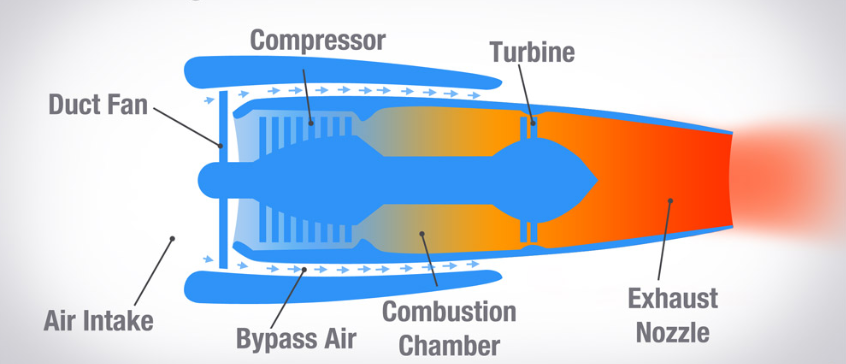
Figure 5: Schematic diagram of the turbofan engine (Cutler, 2017)
The ducted fan is mounted at the front of an engine that provides additional thrust. Also, it helps in the cooling engine and reduces the noise level of the engine. Air is divided into two streams at the inlet, and one flows through the compressor, and the other flows around the combustion chamber, as shown in figure 5. The bypass air produces an additional thrust as the duct fan accelerates it. Likewise, the air entered in the engine through the compressor also produces the thrust. Turbofan engines are very fuel-efficient, quieter, and have attractive aesthetics. However, they are cumbersome, have a large frontal area, and are inefficient at very high altitudes due to the low density of air (Farokhi, 2014).
The turbofan engine is the latest type of aircraft engine and is usually found in commercial planes and high-speed transport. Figure 6 shows a wide-body turbofan engine mounted under the wings of an aircraft capable of producing a thrust of 100,000 pounds (Cutler, 2017).
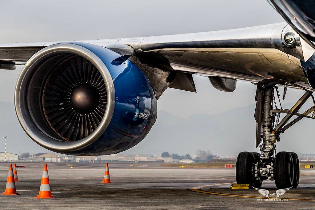
Figure 6: Turbofan engine mounted under the wing of commercial aircraft (Cutler, 2017)
Turboshaft engine
The last type of gas turbine engine is a turboshaft engine; the layout is shown in figure 7. The French company developed the turboshaft jet engine in 1949. The power produced by the turboshaft engine is given to the shaft; most of the energy of the combustion gases is used to drive the turbine instead of providing thrust. The turboshaft gas engine is used in many helicopters, as shown in figure 8. In addition to that, large aircraft use turboshaft engines as auxiliary power units.
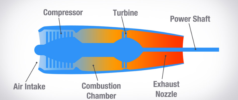
Figure 7: Schematic diagram of the turboshaft engine (Cutler, 2017)
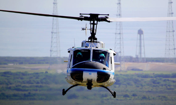
Figure 8: Helicopter equipped with turboshaft engine (Cutler, 2017)
The turboshaft engine has a higher power-to-weight ratio and is smaller than a piston engine. However, they are loud and bulky, and complex due to the shaft and gear assembly.
Gas turbine modules
There are approximately 12 modules in the jet engine; however, in this report, we will discuss compressor and turbine in brief. Figure 9 provides the layout and different parts of the turbofan engine.
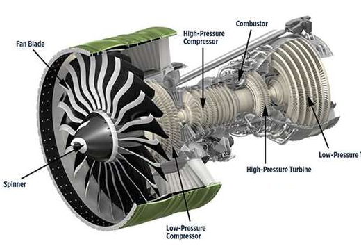
Figure 9: Layout of the turbofan engine (Gardiner, 2015)
Compressor
The compressor is located in the front of the jet engine. Which consist of a fan which has several airfoil-shaped blades. The turbine provides the power to the compressor and the fan. The fan blades provide the acceleration to the air that pushes the air into the engine, and by the bypass duct that provides the thrust according to Newton’s third law of motion. The thrust produced is proportional to the fan’s diameter; however, the fan’s diameter is limited due to the weight consideration of the engine and space. To achieve sustainable design for the jet engines, engineers have developed a new blade design that is wider and has better geometry that improves fuel economy and reduces excessive noise (Shanmuganathan, 2014).
Turbine
The turbine section of the jet engine is located after the combustion chamber. The turbine expands the combustion gases from high to low; therefore, there are fewer stages in the turbine than the compressor. In the turbine section, the velocities of the gas stream are higher, and the blades of the turbine have more curvature. The nozzle guide vanes in the high-pressure section of the turbine have the stator blades used to guide the airflow on the turbine blades; these vanes also expand the combustion gases by generating kinetic energy from pressure energy. The turbine blades are rotated due to the combustion gases that create rotary power provided to the compressor. The gases are passed to the low-pressure nozzle guide vanes, which have the same function as high-pressure guide vanes. The low-pressure turbine blades rotate to provide additional power to the shaft (Shanmuganathan, 2014).
Aviation, gas turbine engines and environmental impact
The environmental impact by the aviation sources could be divided into three categories: in-flight operations, airport operations, and manufacturing and disposal (NRC, 2002). The local quality of the air on the ground and high altitude contribute to global warming due to gas turbine emissions. Also, excessive noise of the jet engines during takeoff and landing affects communities living near the airport. Many researchers have revealed that exposure to excessive noise can affect health. Airport operations involve various operations at the airport itself affecting environmental sustainability, such as jet engine emission during the taxiing, aircraft byproducts, and jet engine maintenance. Finally, the impact of manufacturing and disposal is related to the material used in the jet engine. Most jet engine material is recyclable; however, some might end up in the landfill, affecting the environmental balance (NRC, 2002). The significant effect of a jet engine on the environment is due to the emission of nitrogen oxide that reacts with ozone and methane to change their concertation that contributes to the net warming effect by increasing ozone and by decreasing methane. Another effect of jet engine emission is water vapor and particulate matter. The water vapor and particulate matter can continue to spread into the cloud, contributing to the net warming effect (Balicki et al., 2014).
New gas turbine technologies
The jet engine manufacturing companies continuously strive to reduce the engine’s noise and enhance fuel efficiency through continuous research and development to improve environmental friendliness (Benini, 2011). Some of the concepts of new technologies include (Benini, 2011),
- Developing new fans by reducing the weights and counter-rotating
- Using coating and new lightweight materials on the blades to reduce noise
- Weight saving in the low-pressure turbine by using the design of ultra-high lift airfoil
The wide-chord fan blade
In the 1980s, Rolls Royce developed a wide-chord fan blade for the Boeing B757 mounted with RB211-535. This is by far the successfully applied technology. The original design is recently optimized, as shown in figure 10 (Ruffles, 2001). The recent fan blades are made up of titanium with three layers and bonded together using DB-SPF. It is later inflated that produces a hollow but robust structure. Each blade can produce 70 tons of centrifugal force, which is equivalent to the locomotive’s weight. However, this fan’s assembly is much lighter compared to the one available in the market with competitors.
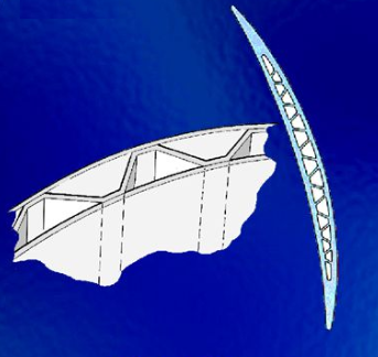
Figure 10: Cross-section of the wide-chord fan blade (Ruffles, 2001)
This technology is currently being used in Airbus’s A380 along with other aircraft. The weight reduction has reduced noise and enhances the engine’s fuel efficiency (Ruffles, 2001).
High-pressure turbine blade
The high-pressure turbine blade is shown in figure 11. The blade comprises an advanced nickel alloy base alloying with cobalt, tantalum, tungsten, chromium, aluminum (Ruffles, 2001). The unique casting process provides the strength that eliminates the usual formation of the solidifying grains in the material. The controlled solidification process produces the single cast of the nickel alloy whit out grain boundaries. The design of the blade is hollow that provides air passage by cooling the component before passing through the protective film of the blade surface. The hollow structure of the fan reduces the weight, which results in enhanced fuel efficiency of the engine assembly (Ruffles, 2001).
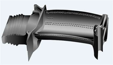
Figure 11: High-pressure turbine blade
Conclusion
The aviation industry is continuously growing and expected to grow exponentially due to an increase in per capita income globally; on the other hand, companies are striving to improve the performance of the jet engine with reduced environmental impact. This report shows a concise analysis of four types of gas turbine engines and their advantages and limitations. Furthermore, the compressor and the turbine module of the jet engine have been discussed briefly. Finally, the environmental impact of aviation, mainly due to gas turbine engines, has been discussed with few examples and a couple of new technologies that have been implemented to enhance sustainability initiatives.
References
Balicki, W., Glowacki, P., Szczecinski, S. and Chachurski, R. (2014). Aviation – environmental threats. Journal of KONES Powertrain and Transport, 21(1), pp.7-14.
Benini, E. (2011). Advances in gas turbine technology. Rijeka: InTech.
Crouch, T. (2009). Lighter than air. Baltimore: Johns Hopkins University Press, in association with the Smithsonian National Air and Space Museum.
Cutler, C. (2017). How The 4 Types of Turbine Engines Work. [online] Boldmethod.com. Available at: https://www.boldmethod.com/learn-to-fly/systems/the-4-types-of-turbine-engines/ [Accessed 22 Dec. 2018].
Farokhi, S. (2014). Aircraft Propulsion. Hoboken: Wiley.
Gardiner (2018). Aeroengine Composites, Part 2: CFRPs expand. [online] Compositesworld.com. Available at: https://www.compositesworld.com/articles/aeroengine-composites-part-2-cfrps-expand [Accessed 22 Dec. 2018].
Hunsaker, J. and Pritchard, J. (1963). Sir George Cayley: The Inventor of the Aeroplane. Technology and Culture, 4(1), p.88.
NRC (2002). For greener skies. Washington, D.C.: National Academy Press, pp.30-36.
Ruffles, P. (2001). Gas turbine technology Powering the future. EARTH, AIR AND WATER, (9), pp.15-17.
Shanmuganathan (2014). Implementation of lean six sigma techniques for cost optimization of aero-engine repair and maintenance. 1st ed. Chennai, India: Anna University, pp.9-18.