VORTEX INDUCED VIBRATION
When a fluid flows past a bluff body (such as a circular cylinder) in a direction which is perpendicular to the axis of the body, boundary layers develop around the body. At a low Reynolds number, the fluid just flows past the body. However as the Reynolds number increases, the vortices tend to separate from the body surface and roll up at the downstream side of the fluid flow. Further increases in the Reynolds number will lead to alternate shedding of vortices due to adverse pressure gradient. This is known as vortex shedding (Downie, 2010). This phenomenon is shown diagrammatically below.
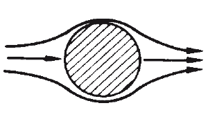
Fluid flow past a circular cylinder at very low Re
Vortices forming at downstream end
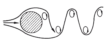
Alternate shedding of vortices
Figure 1 Vortex Street behind a circular cylinder (Harris, 2002). Consequently, as vortices are being shed on the cylinder surface, the cylinder experiences forces which are periodic in nature. These forces cause the cylinder to continuously vibrate as long as vortices are shed. According to Bai (2005), vortex-induced vibration occurs anytime when a sufficiently bluff body is exposed to a fluid flow that produces vortex shedding at, or near, a structural natural frequency of the body. This means vortex-induced vibration occurs when vortex shedding frequency is close or equal to the natural frequency of the body. Continuous periodic vibration of the structure could make it susceptible to fatigue failure. Hence offshore structural members must be designed to prevent VIV.
Important hydrodynamic quantities that influence VIV are:
- Reynolds number
- Lift coefficient
- Correlation of force components
- Shedding frequencies and their interactions
- Added mass (or mass ratio) and damping (Chakrabarti, 2005)
1.1 Types of Vortex Induced Vibration
Basically, there are three types of vortex-induced vibrations. These are:
- In-line Vortex Induced Vibrations
- Cross-flow Vortex Induced Vibrations
- Hybrid Vortex Induced Vibrations
In-line vortex induced vibrations are caused by symmetric shedding of vortices on the surfaces of a bluff body. These usually occur at an average reduced velocity, VR of 1.25. In-line vortex induced motion comprises two regions: 1st and 2nd instability regions. In the 1st and 2nd instability regions, reduced velocities, VR ranges from 1 to 2.5 and 2.25 to 2.5 respectively (Downie, 2010). Vortex-induced vibration does not occur when VR < 1.
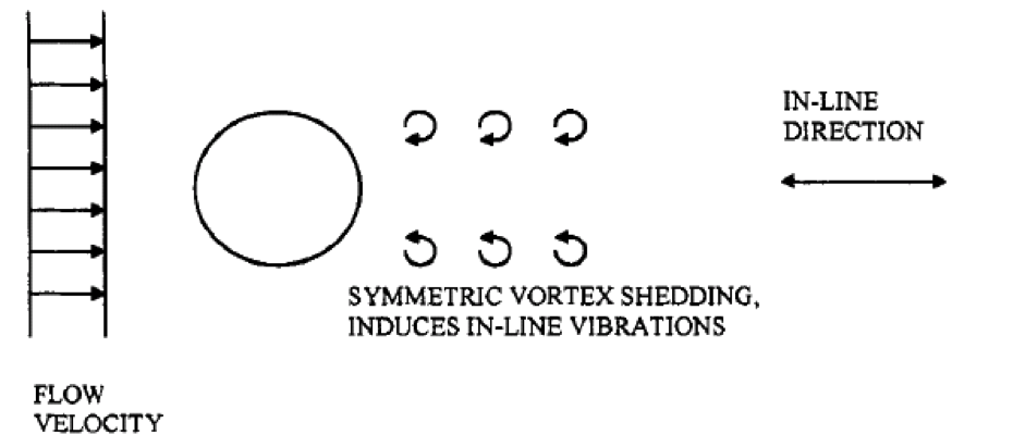
Figure 2 In-line vortex induced vibration (Bai, 2005)
Cross-flow vortex induced vibrations occur when vortex shedding is not symmetric. These vibrations occur at a higher range of reduced velocity in the order of 4.0 and 6.0. Cross-flow vibrations also have greater amplitudes of motion compared with in-line vortex induced vibrations (Bai, 2005).
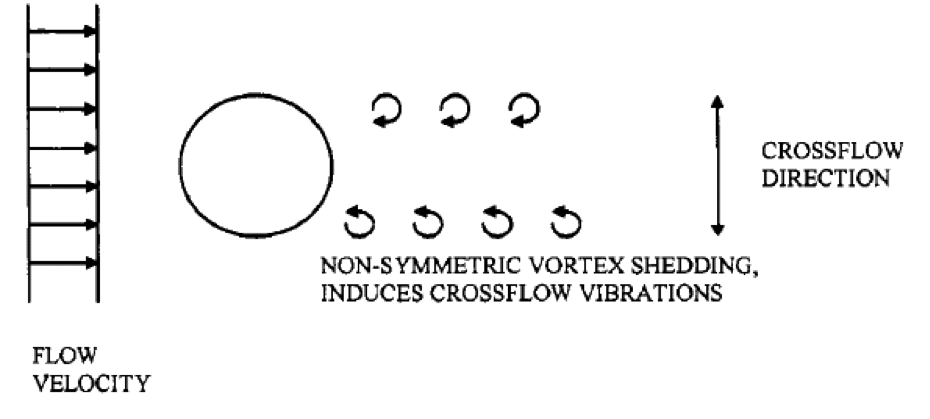
Figure 3 Cross flow vortex induced vibration
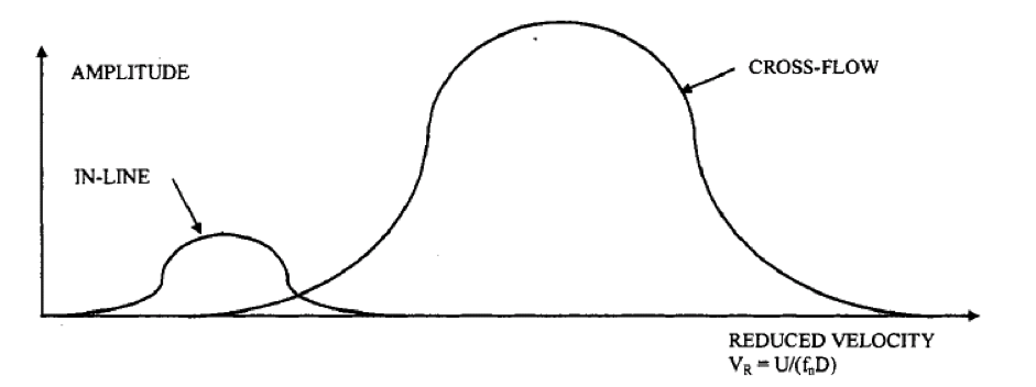
Figure 4 Typical amplitude response as function of reduced velocity (Bai, 2005)
As the name suggests, hybrid vortex induced vibrations are somewhat in between in-line and cross-flow vortex induced vibrations. They are usually a mixture of in-line and cross-flow motions and have a reduced velocity range greater than that of in-line motions but less than that of cross-flow motions.
1.2 Lock-In
Lock-in occurs when the vortex shedding frequency is near the natural frequency of a structure. Vibration of a cylinder in a fluid flow can cause the vortex shedding frequency shift from the natural shedding frequency to the frequency of cylinder oscillation. This is called synchronisation or lock-in. At lock-in, the vortex shedding frequency equals the natural frequency of the nth vibration mode fs = fn. The resultant vibrations occur at or nearly at the natural frequency of the structure. Large amplitude vortex induced structural vibration can result (Harris, 2002).
The region 5≤VR≤7 where lock-in of the vortex shedding frequency to the natural frequency of the cylinder occurs is called the synchronisation / lock-in / capture / resonant region. Consequences of lock-in include increase in correlation length, vortex strength, lock-in band width and in-line drag force; maximum relative amplitude and vortex shedding frequency locks onto the natural frequency. Lock-in can be seen as resonant oscillations (Faltinsen, 1990).
1.3 Prevention of Vortex Induced Vibrations
Different approaches that can be taken to prevent or reduce vortex induced vibrations include:
- Design: This involves designing structural members with a natural frequency that is far away from the vortex shedding frequency.
- Vortex suppression devices: VIV can be prevented in offshore structures by the use of vortex suppression devices. These devices include strakes, shroud, axial slats, fairings, splitter and ribboned cable. These devices act by disrupting the near wake and disturbing the correlation between the vortex shedding and vibration thereby preventing vortex street formation. They do, however, increase the steady drag from that which is measured on a stationary structure (Harris, 2002).
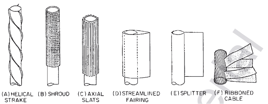
Methods of reducing vortex-induced vibration (Harris, 2002)
Fairings are designed to rotate, so as to align with the current, efficiently minimising vortex shedding and drag loading. Fairings operate most efficiently in structural members which are in a near vertical configuration. Fairings can reduce drag force to as low as one-third of its original value and they suppress VIV almost entirely but they are an expensive option. Less expensive alternatives include strakes. The less expensive alternatives are not as effective, but can be adequate in many instances (Bai, 2005; Chakrabarti, 2005).
Strakes are external ribs placed on the cylindrical structure, most commonly in a helical shape. Helical strakes act to disrupt the flow pattern by creating shorter and weaker vortices. They allow amplitudes of vibration with 10-30% of a diameter. A disadvantage of strakes is their 30-50% additional drag force, which can increase the potential for interference. Although strakes increase drag, they can reduce wave induced fatigue by damping the dynamic response caused by vessel motions. (Bai, 2005; Chakrabarti, 2005). Strakes destroy the correlation of vortex shedding along a structural member.
Shrouds produce a large number of small vortices. Therefore, regular vortex shedding is disturbed and a street of smaller and weaker vortices start to form only several diameters downstream of the body (Naudascher, 1994).
2.0 TECHNICAL SECTION
The aim of this section is to outline procedure needed to check whether structural members of a jacket structure are vulnerable to vortex-induced vibrations. The method employed is that given in the lecture material.
First and foremost, all the structural members will be checked for wind induced vortex vibrations during fabrication as well as transportation to site. After installation of the structure, the members below water surface are acted upon by waves and current. Hence they will be checked for current and wave induced vortex vibrations. However, the members above water surface experience wind action only. This means they may be vulnerable to vortex induced vibrations due to wind and they should be checked for such.
The procedure for checking individual structural members is as follows:
- Wind velocity, V = V10(H/10)0.12
where V10 = 1 minute mean velocity 10m above sea level
H = height above mean sea level (in metres)
- Natural frequency, fn = An (EI/m)0.5
2L2
where An = constant which depends on end fixity
L = length of the member
E = Young’s modulus
I = second moment of area of the member
m = mass per unit length
- Reduced velocity, VR = V
fnD for wind induced vortex shedding
VR = Uc +Uw
fnD for combined current and wave induced vortex shedding
where D = external diameter of the structural member
Uc = current velocity
Uw = wave velocity
- Reynold’s number, Re = VD
ν
where ν = fluid kinematic viscosity
- Stability parameter, Ks = 2m(2ξ)
ρD2
where ξ = critical damping ratio
ρ = density of the fluid
- Check to see if in-line motion occurs from a graph of VR against Ks. If in-line motion occurs, then corresponding value of amplitude should be calculated from a graph of Relative Amplitude against Stability Parameter depending on whether it lies in 1st or 2nd instability region.
- Check to see if cross-flow motion occurs from a graph of Reduced Velocity against logarithm of Reynolds Number.
- If cross-flow motion occurs, its amplitude, y should be calculated as follows:
Iterate design lift coefficient, CLj until convergence is achieved. First take I/Io = 1. Calculate CLj and y/D. Read off turbulence factor, I/Io from graph of I/Io against y/D and put the value back into the equation for CLj.
CLj = CLo Io (I/Io)
y = CLj
D 4KsS2
where CLo = base lift coefficient
CLo = 0.29 if Re > 4×10⁵ and = 0.42 if Re < 4×10⁵
S = Strouhal number
Io = correlation length factor which depends on the member fixity
- Maximum stress fb = Kn ED y
L2
where Kn = constant depending on fixity
- Stress range = 2 fb
- Stress hot spot range, σH = stress range x stress concentration factor
- Number of cycles to fatigue failure, N = 10(12.1638-3logσH ) (σH is in N/mm2)
- Time to failure = N/fn
Bai, Y., Bai, Q. (ed.) (2005) Subsea Pipelines and Risers: Vortex-induced Vibrations (VIV) and Fatigue. Elsevier
Chakrabarti, S. (ed.) (2005) Handbook of Offshore Engineering. Part II: Drilling and Production Risers. Elsevier Ltd.
Downie, M. J. (2010) MAR8020 Lecture note: Vortex Induced Vibrations Design Brief. Newcastle University, pp:
Faltinsen, O. M. (1990) Sea loads on ships and offshore structures. Cambridge University Press.
Harris, C. M., Piersol, A.G. (ed.) (2002) Harris’ Shock and Vibration Handbook (5th edition). McGraw-Hill.
Naudascher, E., Rockwell, D. (1994) Flow-induced vibrations: An engineering guide. Rotterdam: A.A. Balkema Publishers.