Literature Review: Optimization Of Demagnetization Process
Number of words: 3779
Magnetic fields cause the physical phenomena known as Magnetism. The effect of magnetism can be observed easily in the ferromagnetic materials such as iron that has a strong affection towards the magnetic field and can be magnetised easily to become permanent magnets. However, this magnetic property of material may interfere during many engineering applications such as measurements, calibration as well as the operation of sensitive mechanical devices. Also, it has the capability to erase the data from electronic devices such as hard disks. Therefore, it is necessary to demagnetize the material before using it in engineering and electronic applications (Furlani, 2009). The process of eliminating the magnetism from the material is called the demagnetization process (Smith, 1917). This literature review includes the background of the demagnetization process along with its need and methods of demagnetization. Also, this section discusses different electrical steel types, such as Grain-oriented electrical steel and non-oriented electrical steel and their properties. Demagnetization of grain-oriented steel has been discussed in brief, whereas the case study depicts the equipment and the method used to demagnetize HTS bulk in the iron core.
Background
Magnetization is a physical phenomenon due to the orientation of the crystals in the magnetic material. Magnetic saturation caused these crystals to be always magnetized. Microscopic photographs of iron are shown in figure 1. Due to increasing magnetic field H, the domain in iron changes its size as shown. The domain growth in the orientation of the magnetization will grow in the direction of an external field, on the other hand, the shrinking in the domain that opposed to the external field. Therefore, domain growth can be observed in terms of the movement of the domain wall. Figure 2 shows the magnetization curve plotted with ‘H’ Magnetization on the horizontal coordinates whereas ‘B’ flux density on the vertical coordinates considering residual magnetism of the ferrous material to be zero, which is also referred as “Virgin Curve”. When magnetism H increases up to the initial curve of magnetization then the domains are not aligned with the external field direction. In this scenario, the domain rotation takes place in which domain rotate in the direction of the external field (Stanley, 2011).
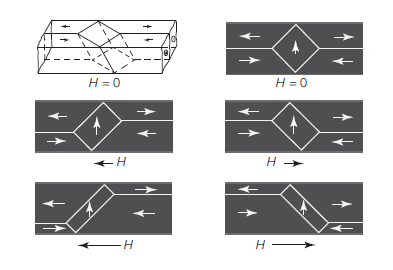
Figure 1: Changing domain of magnetic iron (Stanley, 2011)
Figure 2: Changes in magnetic flux density and magnetic field intensity with time (Sheikh, 2018)
The vertical domain shown in figure 1 is shrinking and eventually, it changes the direction in the orientation of the external field through domain rotation. In the process of magnetization, the crystallite domain saturated at the grain boundaries or the discontinuities within the structure of a metal. The structure of the metal is oriented according to the direction of the external magnetic field applied. Therefore, due to the disappearance of the domain wall towards the saturation, decrease in the number of the domain within the magnetized object can be observed. On the other hand, demagnetization is the process of rearranging the domains which are fully magnetized to reduce or completely remove the magnetism from the material. It is necessary to note that, even if the net effect of domain rearrangement is ‘demagnetization’ of that specific material from outside, but the domains inside the material remain completely magnetized, the rearrangement or change in the direction of the field causes the demagnetizing effect. By using very fine magnetic powder, it is possible to analyse the domain wall under the microscope due to the magnetic flux leakage effect is also known as MFL. Many sheets of steel retain the magnetism, many daily life ferromagnetic products can be checked with the Tesla meter, the reading will show that many products are discreetly magnetized. The retention of the magnetism is known as residual magnetism, retentivity or remanence denoted by Br (Stanley, 2011).
Need for demagnetization
There are many reasons for the demagnetization of the magnetized component usually manufactured from the ferromagnetic material, especially in the field of manufacturing and the inspection (Bozorth, 2003). The reasons to demagnetise the material and components are given below (Stanley, 2011),
- To avoid interference of the magnetised component during the machining operation of ferrous material, the magnetic material can force metal chips to be magnetized and it may adhere to the cutter surface and reducing the quality of the product as well as reducing the life of the cutter.
- The residual magnetism in the component is not desirable especially in the measuring devices as it may attract small ferromagnetic particle and interfere with the measuring procedure.
- To avoid interference during the welding operation by using ionized plasma. The magnetic field can deflect the plasma.
- To avoid friction between the moving ferromagnetic part, for an instance, residual magnetism in the moving ferromagnetic part may attract small metal particle and interrupt operations.
- Magnetized particles are hard to clean from the roots of threads as well as unreachable corners of the machine, therefore it needs to be demagnetized for the sake of easy and efficient cleaning.
It is also necessary to demagnetize the instrument used to analyse the magnetic property of the components, and material as it may retain the magnetic property of the previously inspected component or material due to the hysteresis (Bozorth, 2003). One of the good examples where demagnetization is required is after the “wet fluorescent magnetic particle test” inspection on the tube threads, also prior to welding ends of line pipe (Stanley, 2011).
Methods of demagnetization
There are different methods available for the demagnetization process. Often, the type of method used depends upon the size of the part undergoing the demagnetization process. The magnetic permeability of the material defines the amount of magnetism part has. Very basic magnetism experiment carried out in the physics class in the school by putting 2 mm diameter demagnetized rod in the earth’s magnetic field. This demagnetized rod is gently tapped with a hammer. The action provides enough energy to add to the domain structure of the demagnetized rod by realigning them in the field direction of the earth’s magnetism. The resulting magnetic field of the newly magnetized rod can be determined by the Tesla meter working on the principle of Hall effect, (holding tesla meter at the ends of the magnetic rod). It means, it is virtually difficult to fully demagnetize any material, however, it is possible to fully demagnetize the material by heating it above its Curie temperature or a curie point and cooling with keeping the axis of the material East-West (Stanley, 2011).
Demagnetization by heating the material
The temperature above which ferromagnetic material loses the property of magnetism and it is replaced by induced magnetism. Pierre Curie first demonstrated the loss of magnetism at the material’s critical temperature, therefore, the temperature is named after Curie (NAS, 1995). Curie temperature of the steel is 1420 0F or 770 0C (Gillespie, 2018). The tiny magnetic zone within the steel known as “Domains” disappears due to the extreme vibration at the Curie temperature. It is necessary to carry out the process of demagnetization of steel by heating in a furnace, which should be located at the robust, heatproof as well as the well-ventilated area. The steel object, material that needs to be demagnetized is placed in the furnace whereas curie temperature of the steel is set. It is required to hold the steel object at least for 5 minutes at the Curie temperature, then cooling is carried out in room temperature (Gillespie, 2018). To partially demagnetize the material, it is required to heat the metal at the lower temperature than that of Curie point. Also, partial demagnetise can be obtained by keeping the elongated object aligned to North-South in the magnetic field of the earth, which is approximately 0.02mT (Stanley, 2011).
Demagnetization by using AC current
Demagnetization of the ferromagnetic material can be achieved by keeping the material in solenoid coil through which alternating current is passing; approximately 50 Hz to 60 Hz. The object is then removed from the electric field, away from a coil. A demagnetizer (degausser) is used to demagnetize the ferromagnetic material by using AC field. Once the object is kept in the degausser, an electric current is passed through the solenoid, that produces the magnetic field. Now, when the object is in the range of one or two inches from the degausser surface then alternate the polarity of the current demagnetizes the object. The object can be used to pick up a small metal object to check whether the object is demagnetized or not (Gillespie, 2018).
As shown in figure 3, the road is subjected to constant reversing as well as decaying of the magnetic field.
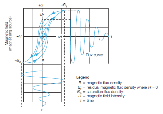
Figure 3: Reversing and decaying of the magnetic field (Stanley, 1997)
As shown in figure 3, the object starting from Br is taken to (-Bs) which is a saturation flux density, and then to +Bs while continuously changing the value of B until the lowest value of B is attained. Now, the theory of eddy current states that the AC current can penetrate the material for approximately “three skin depths”, skin depth is also known as “effective depth of penetration”. Therefore, according to this theory, the current penetrates the steel object, approximately 1 mm to 3 mm assuming 50 Hz to 60p Hz standard frequency of power. Therefore, the material beyond 3 mm will not have any effect of reversing alternating current field which is responsible for the domain scrambling that results in the demagnetization (Stanley, 1997).
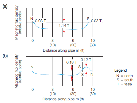
Figure 4: Demagnetization by using reversed field coil, a) before & b) after (Stanley, 2011)
Figure 4 shows the result obtained by Stanley (2011) during the process of demagnetization by using reversed field coil. The test was carried out on the steel pipe of 10 m long. Figure 4a shows the magnetism of the pipe before the demagnetization which reaffirms that the pipe has the longitudinal magnetism at the halfway mark, 11.4 kg. or 1.14 T as well as at both the ends where the meter is measuring the strength of the external field, which is approximately 300 G or 0.03 T. The demagnetization of the steel pipe obtained by reversing the field current, which is shown in the figure 4b, and it is 1.8 kg. or 0.18 T at the halfway mark and 1.2 kg. or 0.12 T at one end.
Demagnetization by using a hammer
The demagnetization of the ferromagnetic material can also be achieved by physical methods such as knocking or hammering. The internal field can be appeared at the surface of the object or the material by hammering action. The inner magnetization of the material re-rotates domain to the nearest surface that generates the external field. The process of demagnetization through hammering is, the non-metallic surface is used to place the ferromagnetic object, and the object is hammered sharply by using a hammer. The energy is transmitted into the steel that helps to rearrange the atoms which result in lowering the magnetism of that object. It is necessary to carry out this procedure normal to the magnetic field of the Earth, or in East-West direction. The magnetism of the object can be checked by picking up the small metallic object if the magnetism is still present then the process is repeated for several times (Gillespie, 2018).
Electrical steel types and their properties
The steel that contains the silicon percentage between 3-6% referred to as Electrical steel. Electrical steels are also referred to as Silicon steel, Silicon electron steel, transformer steel or lamination steel. A most important factor in electrical steel is its Silicon percentage. The magnetic properties of the electrical steels get better with the addition of the silicon, although, silicon percentage above 6% makes the steel brittle and difficult to work with. There are two main categories of electrical steel, oriented electrical steel and non-oriented electrical steels (NGO). Oriented steels are further classified into High permeability (HiB) and Grain oriented steels (GO) (Bemmer, 2013).
Non-oriented steels are made without any special procedure to control the orientation of the crystal and has 2 to 3.5% of silicon level (Bulín et al., 2017), on the other hand, grain-oriented steels are made with special procedure so that the properties are developed in the direction of rolling and has 3% of silicon level (Kumano, Haratani and Ushigami, 2004).
The magnetic properties of non-oriented electrical steel are spread in all the direction (Kubota, 2005) whereas for grain-oriented electrical steel the magnetic properties are only developed in the direction of rolling due to the stringent control over the crystal orientation (Kumano, Haratani and Ushigami, 2004).
By using the stringent process, the magnetic flux density of the grain-oriented electrical steel is increased by 30% in the direction of the rolling whereas magnetic saturation is decreased up to 5%. The grain-oriented electrical steel is used in the core of a transformer used in power distribution channels. The production of grain-oriented steel is usually in the coil form. Later these coils are cut into the laminations to become an integral part of the transformer core. Non-oriented electrical steel is comparatively cheaper than that of grain-oriented steels. Non-oriented steels are preferring in the situation where cost has prime importance than that of efficiency, also an application where the magnetic flux is inconsistency, for example, generators, electric motors which has moving parts. Figure 5 shows the cross-section of the grain-oriented steel depicting magnetic domain as well as domain walls, figure 6, on the other hand, shows the non-oriented steel (Sievert, 2000).

Figure 5: Grain-oriented steel showing magnetic domain wall (Sievert, 2000)
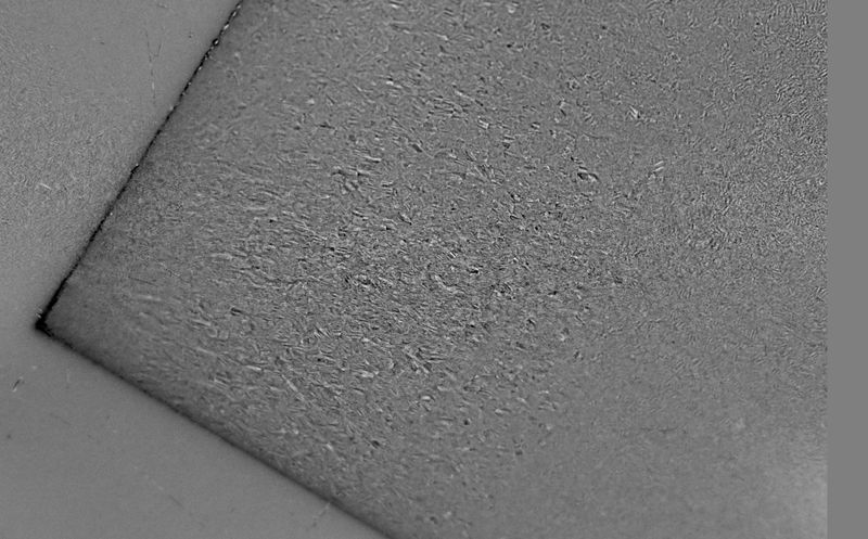
Figure 6: Non-oriented steel showing magnetic domain wall (Sievert, 2000)
The electrical steel has relative permeability approximately 4000 times as compared to vacuum. Heat treatment of electrical steel defines the magnetic properties, as hysteresis loss decreases with the increase in average size of the crystal. The cost of electrical still is much more than that of mild steel, approximately twice than mild steel since 1981 (Jump, 1981). It is possible to reduce the magnetism of the electrical steel by using a mechanical method of scribing the surface or by using LASER, reducing hysteresis losses in the core of an assembly (Lhorbe, 1981).
Demagnetization of grain-oriented electrical steel
The demagnetization of the grain-oriented electrical steel can be carried out by the simple method of using the AC sinusoidal excitation by applying maximum amplitude and further reducing it slowly to zero. Figure 7 shows the domain and their orientation along with the eddy current movement. Initial current in the winding of the transformer should be higher than the highest current that can be handled by the transformer to attain “ideal” demagnetization of the electrical steel. Therefore, the voltage required for the nominal frequency is higher than that of the complete rating. This is practically impossible as the amount of power required is beyond the capacity of the demagnetizer (Mehta and Mehta, 2007).
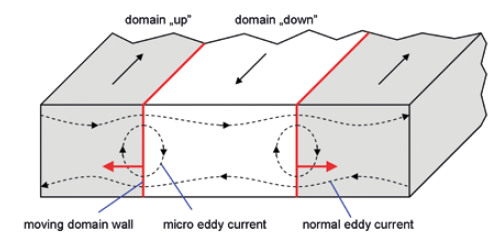
Figure 7: Domain orientation in grain-oriented steel (Tata, 2015)
Therefore, the different methodology had to be considered for the demagnetization, such as the application of DC excitation to the windings. The polarity is then switched while the amplitude is decreasing, the method is called as switched- DC method. This approach generates the non-sinusoidal AC current resulting in demagnetization like the demagnetization by AC sinusoidal method. This approach extremely reduces the need for excess power. In addition, demagnetization can be carried out successfully with the reduced voltage required only to drive the reversible direct current through the winding resistance (Zurek, 2015).
Case study: Demagnetization of HTS Bulk in Iron Core
A case study is carried out for the sake of understanding the practical application of the demagnetization process of HTS bulk in an iron core (Grain-oriented electrical steel). Hight Temperature Superconductors have a capacity to act as powerful permanent magnets due to which HTS is used in the variety of applications in the electrical industry (Berger et al., 2016).
Equipment
This experiment consists of a bulk sample, an iron core, inductors as well as current sources to demagnetize the HTS bulk within the iron core. The experiment is carried out at the 77 K which is the temperature of liquid nitrogen as the temperature of the HTS is 92 K (Berger et al., 2016).
- Sensor and HTS Bulk
- The laminated iron core containing grain-oriented electrical steel, which is insulated, and the thickness of 0.35 mm. Figure 8 shows the structure of a laminated core. As shown in the figure, the HTS bulk is placed above the coil, which is above the central lag.
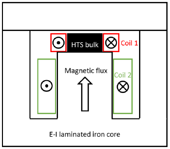
Figure 8: Laminated core structure (Berger et al., 2016)
- Copper coils are used to generate an electrical field to demagnetize the HTS bulk. There is a pair of the copper coil, one is round wrapped around the HTS bulk (17turns) whereas rectangular one is wrapped around the central leg of the core (42 turns). Both the copper coils are connected in series; therefore, a total number of turns is The assembly of the entire system used in this experiment is shown in figure 9 (Gony et al., 2015).
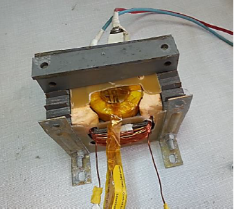
Figure 9: Assembly of the system (HTS bulk in iron core wound in copper coils) (Berger et al., 2016)
- Source of current supplied to the copper coil, the capacitor with the bank of 24 is used with 80 ml The maximum voltage of the capacitor is 300 V whereas the capacitor is designed to withstand 50 kA. The thyristor with the maximum current of 15 kA is used to initiate the discharge current by triggering. The HTS bulk is subjected to the AC magnetic field by using the 1000 W bipolar power supply which is manufactured by KEPCO. It is possible to increase the values of the current as well as a voltage by ±50 A and ±20 V along with the 443 Hz sinusoidal wave frequency (Gony et al., 2015).
Demagnetization process
To understand the superconducting magnets in the synchronous motor it is significant to analyse the effect of demagnetization on the magnetic field of an HTS bulk located within the laminated iron core. It is difficult to assess the HTS bulk subjected to waves and corresponding amplitude in the real synchronous motor (Berger et al., 2016). The field of demagnetization coming from the stator coil is in the form of a pulsating magnetic field. In an actual motor, when a short circuit occurs that produces a pulsed magnetic field due to the armature current. This pulsed magnetic field demagnetizes the superconducting magnets, in this case, HTS. In the experiment, however, the magnetic core is fixed unlike in the actual motor, also it is difficult to anticipate the amplitude of the “pulsating magnetic field”, although, the range of 150 mT to 200 mT considered to be reasonable for the conventional configuration. The HTS located in the iron core is subjected to the AC sinusoidal magnetic field, at the maximum amplitude of 120 mT along with the variable frequencies. Hall probe was used to measure the value of the maximum amplitude which is located at the centre of the surface of HTS bulk. Therefore, to demagnetize the HTS bulk this value of 120 mT can be applied directly to the sample surface (Berger et al., 2016).
Conclusion
This section discusses the theory of the magnetization that is later related to the demagnetization process. The need of demagnetization in the field of manufacturing and instrumentation has been discussed by providing real-life examples. The primary methods that have been used to demagnetise the material have been discussed in detail, however, it is necessary to note that chemical and thermal methods are being developed in order to demagnetize the ferromagnetic materials. This section also shows in detail the types of electrical steels, their properties and applications along with the example of the demagnetization. A case study of demagnetizing HTS bulk in the iron core has been discussed to understand the concept of the pulsed magnetic field that demagnetizes the magnets.
References
Bemmer, V. (2013). The Properties of Electrical Steels and Their Coatings. 1st ed. Cardiff: Cardiff University, pp.2-20.
Berger, K., Gony, B., Douine, B. and Leveque, J. (2016). Magnetization and Demagnetization Studies of an HTS Bulk in an Iron Core. IEEE Transactions on Applied Superconductivity, 26(4), pp.1-7.
Bozorth, R. (2003). Ferromagnetism. Hoboken, New Jersey: John Wiley & Sons.
Bulín, T., Švábenská, E., Hapla, M., Ondrůšek, Č. and Schneeweiss, O. (2017). Magnetic Properties and Structure of Non-Oriented Electrical Steel Sheets after Different Shape Processing. Acta Physica Polonica A, 131(4), pp.819-821.
Furlani, E. (2009). Permanent magnet and electromechanical devices. San Diego: Academic.
Gillespie, C. (2018). How to Demagnetize Steel. [online] Sciencing.com. Available at: https://sciencing.com/demagnetize-steel-12741.html [Accessed 6 Jan. 2019].
Gony, B., Berger, K., Douine, B., Koblischka, M. and Leveque, J. (2015). Improvement of the Magnetization of a Superconducting Bulk using an Iron Core. IEEE Transactions on Applied Superconductivity, 25(3), pp.1-4.
Jump, L. (1981). Transformer Steel and Cores. Federal Pioneer BAT, 1(1).
Kubota, T. (2005). Recent Progress on Non-Oriented Silicon Steel. steel research international, 76(6), pp.464-470.
Kumano, T., Haratani, T. and Ushigami, Y. (2004). Grain Boundary Characteristics in Grain Oriented Silicon Steel. ISIJ International, 44(11), pp.1888-1893.
Lhorbe, R. (1981). Steel No Lasers Here. Federal Pioneer BAT, 1(1).
Mehta, V. and Mehta, R. (2007). Principles of electrical machines. 2nd ed. New Delhi: S. Chand & Co.
NAS (1995). Biographical Memoirs. Washington: National Academies Press.
Sheikh, A. (2018). Magnetization Curve. [online] Electrical Academia. Available at: http://electricalacademia.com/electromagnetism/hysteresis-loop-magnetization-curve/ [Accessed 6 Jan. 2019].
Sievert, J. (2000). The measurement of magnetic properties of electrical sheet steel – survey on methods and situation of standards. Journal of Magnetism and Magnetic Materials, 215-216, pp.647-651.
Smith, A. (1917). Demagnetization of Iron. Physical Review, 10(3), pp.284-290.
Stanley, R. (1997). Simple explanation of the theory of the total magnetic flux method for the measurement of ferromagnetic cross sections. NDT & E International, 30(1), p.35.
Stanley, R. (2011). Demagnetization. The American Society for Nondestructive Testing, Inc, 10(3), pp.6-8.
TATA (2015). Grain-Oriented electrical steel. [online] cogent-power.com. Available at: https://cogent-power.com/products/grain-oriented-electrical-steel [Accessed 6 Jan. 2019].
Zurek, S. (2015). Demagnetisation of grain-oriented electrical steels (GOES). Transformers magazine, 2(4), pp.31-35.